Pressure Vessel FEA
Finite element analysis has been widely used in pressure vessel design where code formulas are not applicable. Interpretation of the FEA results shall be performed to ASME Section VIII, Div. 2. For CRN registration projects using stress analysis, the FEA report has to be accepted by the review engineers at the jurisdictions.
Model #1: Pressure Vessel Design
- This analysis is to show how central stay affects stresses in formed head and tubesheet. Use of stay effectively reduces required thickness for tubesheet. However, it also generates additional bending stresses in head. A repad is needed on head to limit peak stresses within allowables. It provides an option for tubesheet design. Material thickness and loads applied are not our concerns in this show, which are omitted.
- Material for analysis is SA-516 70. Pictures below present partial results of the analysis. Interpretation to stresses at different locations is simlpy illustrated to ASME Section VIII-2 rules.
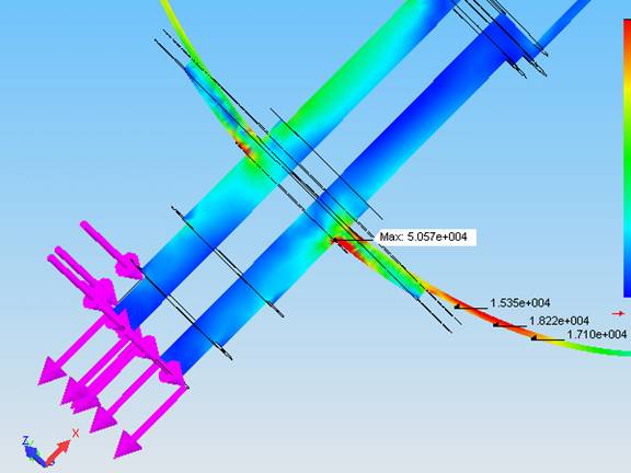
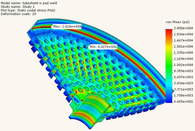
- When model is relatively too big, more time will be needed for FEA runs if reasonable mesh size is used and tubes are modeled. The alternative is to create a seperate model for tubesheet only with tubes included. The last picture shows such a model and stress distribution around tube holes.
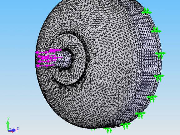
Mesh: 40mm, corner: 10mm
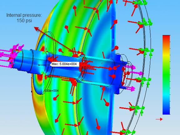
Model pressurized inside, additional forces added on end
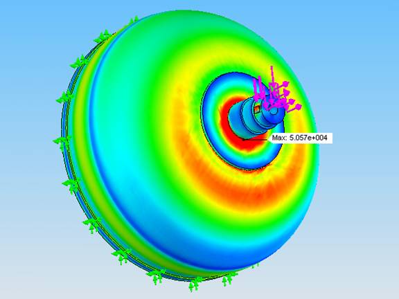
Stresses > 20,000 psi (membrane limit Sa) in red
At corners: (PL+Pb+Q)<3Sa, PL<1.5Sa; General locations: Pm+Pb<1.5Sa, Pm
Model #2: Heat Exchanger without Shell
Introduction:
This is a further discussion on Model #1. In that model, a repad is applied on the head to reduce local stresses at openings. The question is: can we remove the repad if ribs are installed inside the head to provide support? The answer is yes — ribs are structurally capable of carrying condensate out of the head.
Design Conditions:
Design Conditions:
Vessel ID: 2200mm Shell thickness: 20mm
Head: 2:1 SE, 18mm thick (after forming), SA-516 70 welded to tubesheet and SE head
Manhole on head: 300×400mm, 25mm thick (SA-36 rolled plate)
Drain: reverse flange, 52mm ID, 59mm wall, 25mm thick, SA-36 pad
Central pipe: 250mm OD, 26mm thick (passes through head and tubesheet)
Design pressure: 150 psi
Corrosion allowance: 3mm
X-ray: RT-3
Calculation Discussion:
Calculation Discussion: This is a non-code heat exchanger evaluated using FEA and ASME formulas. Due to the support provided by ribs and the absence of a shell side, the use of UHX is not applicable. While UG-34 and UG-39 can be used to assess tubesheet thickness, these methods are conservative because they do not account for the structural support of the ribs. Instead, ASME Section VIII-2, U-2(g) FEA-based evaluation is used for a more realistic and optimized thickness calculation.
Results: UG-34 and UG-39 require 156mm thickness. TEMA standard requires 80mm. The FEA analysis, accounting for support from ribs, shows required thickness around 65mm.
Stresses in tubesheet are below 1.5 × Sa (Bending stress limit), acceptable.
Model #3: Platform Support Attachment
Support configuration not covered by WRC107 or NozzlePro can be analyzed by FEA.
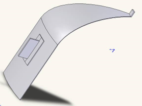
WRC107 Simulation
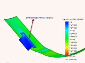
NozzlePro Analysis
Model #4: Irregular Pressure Vessel Design
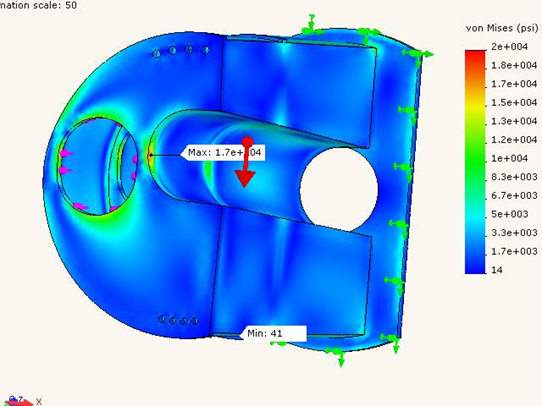
This model demonstrates stress concentration regions around complex nozzles and reinforcement pads. FEA helps visualize stress flow and confirm code compliance.
Model #5: Structural Design
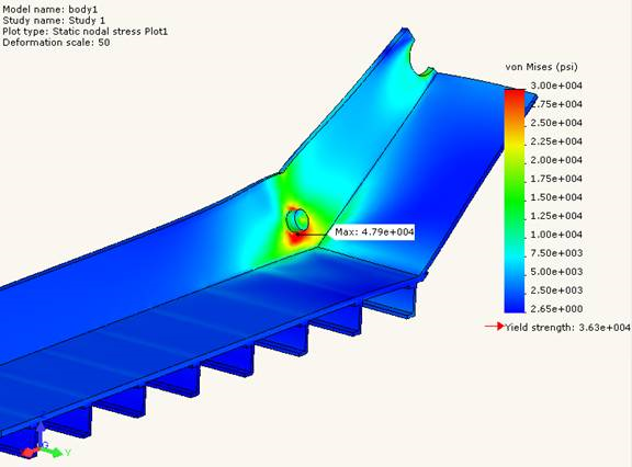
- This model is for an ash conveyor underneath power boilers. A quarter of the frame is modeled. 3D solid element is used in analysis. Symmetry constraints are selected for mid planes. Half circle on top for transmission shaft is the area to take loads. Guide wheel for the chain at bottom of the slope is anchored in direction perpendicular to bottom plate to ensure the model is fully defined.
- Results show stresses around guide wheel are over yield point. Strength design shall be focused on this area. In this case, local reinforcement might be needed to prevent material from yielding.